
| Adding a Water Pump Switch to the Bath of Our 2006 Itasca Navion |
| (and never again having to ask your mate to "turn on the pump") |
|
by Ellsworth Chou
|
Even after owning our 2006 Itasca Navion for a little over a year, my wife and I still frequently found ourselves asking each other from inside the bath to turn the water pump on during roadside relief stops, having forgotten to turn it on. I wondered why Winnebago had not included a pump switch inside the bath, and decided to add one myself.
While rolling down the road in the Navion during a 7,800 mile trek in 2010, I worked out a theoretical solution for adding this third pump switch, the original switches being located on: 1) the Systems Monitor Panel in the galley, on the forward side of the wardrobe cabinet wall above the stove; and 2) outside, on the Water Service Center panel beside the fresh water fitting and the fresh water diverter valve. While this outdoor switch is convenient when using the shower head in the outdoor Water Service Center, we use that pump switch infrequently. The bath, we use many times a day (as we like to say, "The two best things about traveling in an RV are #1 and #2").
After noodling this for a while, I hit upon a somewhat simple way to add a new, third switch to create a three-switch system that allowed the same behavior as the original two-switch layout. Users should be able to turn the pump on or off at any of the locations, regardless of the positions of the other two switches. And there needs to be an indicator light at the new switch location that reflects the pump's current on/off state.
Fortunately, the Navion's existing pump switch wiring was as I'd guessed. The SPDT switch closest to the power source in the galley routes the positive side of 12VDC to one of two possible wires, and the second switch in the Water Service Center then selects which of the two wires is routed to the positive terminal of the pump.
Play the video below to see the original switching system:
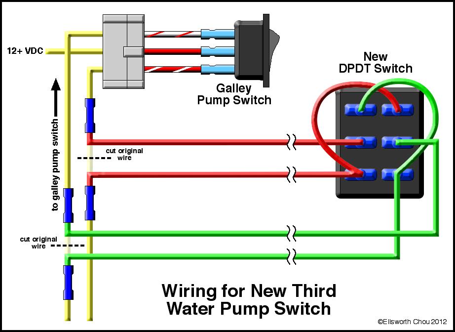
My solution to add a third switch intercepts these two wires between the existing switches with a DPDT (double-pole, double-throw) switch. This switch is wired so to produce one of two conditions: 1) allow the current states of the two wires to pass through as normal, or; 2) swap the two incoming wires to the two outgoing. Thus installed, the behavior of all three switches - the two original and the new one - are identical. The pump can be turned on or off at any of the stations. Perfect.
Play the video below to see the new switching system:
As with the original two switches, any switch's physical position is NOT an indicator of whether the pump is on, so a new pump power indicator lamp for the new third switch position is also necessary.
So my initial tasks for installing a "Third Switch" were:
I decided it would be nice to have the same kind of switch as the one in the Water Service Center. Its integral LED indicator was particularly appealing for a tidy installation. A little online research identified that switch as being made by Blue Sea Systems, made for marine applications. The company's website listed only a single DPDT model, the Contura 8275. However, it did NOT feature an integral LED. I'd been puzzling over how to make an integral LED work anyway, since this unique application reverses the electrical polarity at every terminal on the switch. Unlike incandescent lamps, light-emitting diodes are polarity-sensitive - reversing the electrical polarity results in everything from nothing happening to the diode violently failing.
I found the switch for sale at Amazon.com for $14.99, and also noticed a related item listed as a "Contura 8268 Single Mounting Bracket." I realized this was a plastic "receiver" which is installed into the desired location, and the switch then slides into this mount. I ordered both the switch and bracket.
I was disappointed that I wouldn't have a fancy integral indicator lamp, but I liked the marine-spec switch in the high-humidity bath environment. I decided to simply install a 12-volt LED indicator and run a pair of dedicated wires all the way from the pump itself. Because the LED draws very little current, I could add very small-gauge wires alongside the four wires from the original indoor water pump switch to the Third Switch.
I chose to locate the Third Switch on the wall opposite the commode at about knee-height. Not only would this be, uh, convenient, but allowed me to route the wires through both sides of the wall into the under-bed storage area in our Navion 23J. I'd mount the LED directly above the switch in its own hole.
PARTS LIST
(click and hold on images on this page to enlarge them)
 |
 |
|
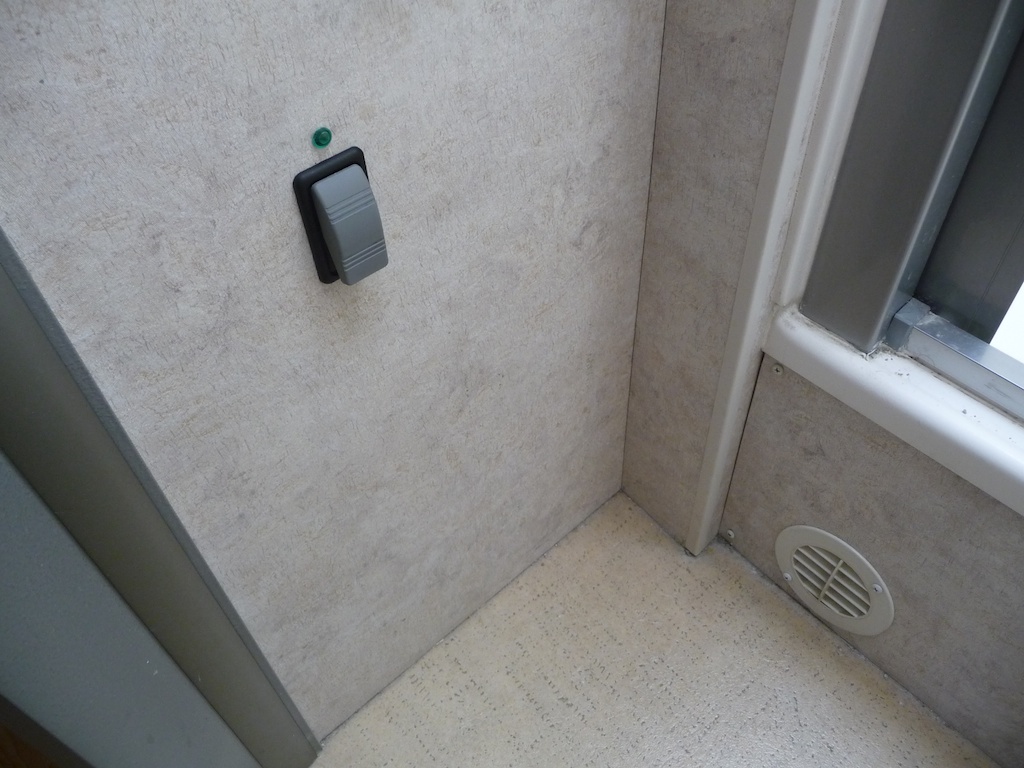
Location of the new switch in bathroom
|
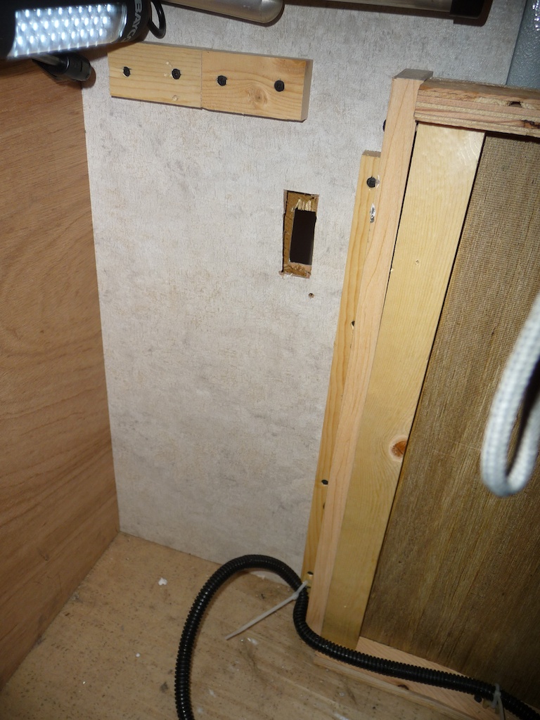
Opposite side of switch location as viewed from 2006 Navion 23J underbed storage area
|
To identify the two wires to which the Third Switch would be spliced, I removed the screws holding the Systems Monitor Panel to the wall above the range top. The existing pump switch has three wires attached: the "common," and what we'll call the "A wire" and "B wire." I ran a long test wire from the ground lug on the 12 volt power controller/fuse panel to a Volt-Ohm Meter (VOM) and probed the wires at the existing switch.
Here were the wire color codes for the Water Pump Switch at the Galley Indicator Panel our '06 Itasca Navion:
| Location | Function | Wire Color |
| Top terminal | 12+ VDC switch in position "A" | Red/White Trace |
| Center terminal | 12+ VDC | Red |
| Bottom terminal | 12+ VDC with switch in position "B" | White/Red Trace |
So 12 volt power for the water pump comes into the system at the center "common" terminal of the Galley Water Pump Switch, and the switch then sends the current to one of the two other terminals. Which of the two terminals does what isn't important. All I really needed to identify was the two switched wires (in our case, red/white and white/red) to which I'd incorporate my switch.
(click and hold on images on this page to enlarge them)
 |
 |
|
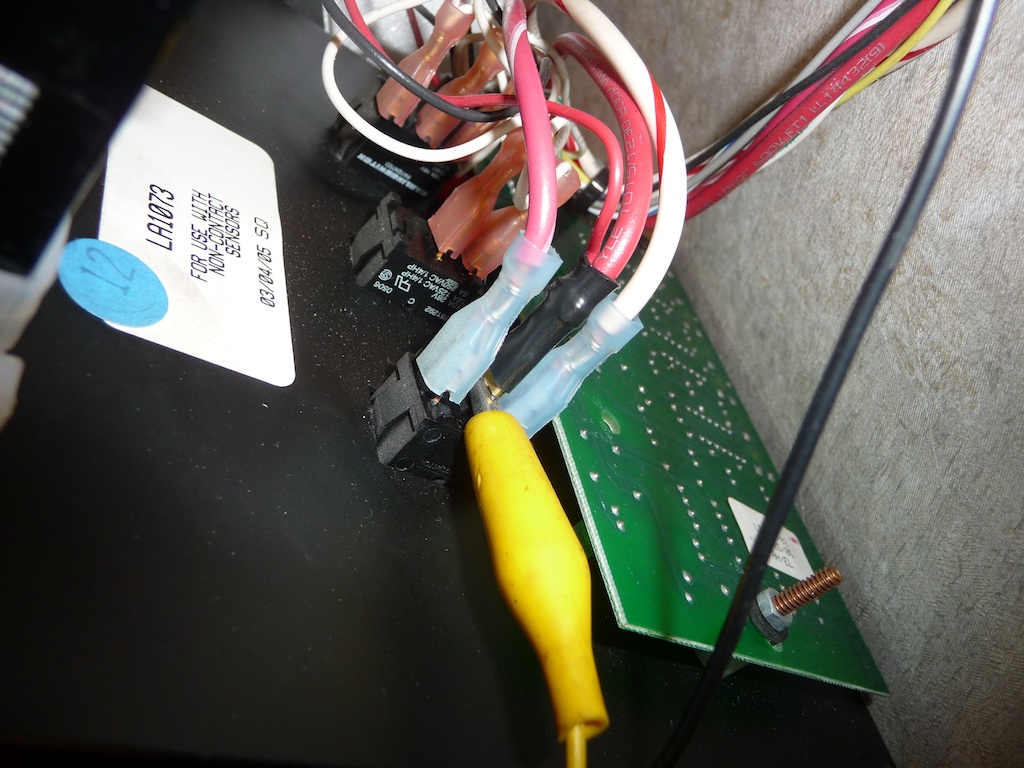
Tracing the exisitng pump switch wires in the galley
|
The color codes get lost on the other side of this multi-pin connector, where every wire is yellow
|
Unfortunately, these two color-coded wires terminate in a 12-conductor connection block, and on the other side of this block Winnebago uses all identical yellow wires. These wires join a large bundle of more yellow wires after passing down inside the hollow wall between the galley and the inside of the wardrobe cabinet. You may be able to isolate the two yellow wires of interest by physically starting at the other side of the connector behind the Galley Indicator Panel, wiggling and pulling each wire while an assistant looks at the bundle of yellow wires down in the water heater access hatch (below the wardrobe cabinet on the '06 23J). Working alone, I resorted to using a Volt-Ohm Meter in "continuity test" mode and a long test jumper, poking a straight pin through the insulation of the mysterious yellow wires until the VOM beeped.
 |
 |
|
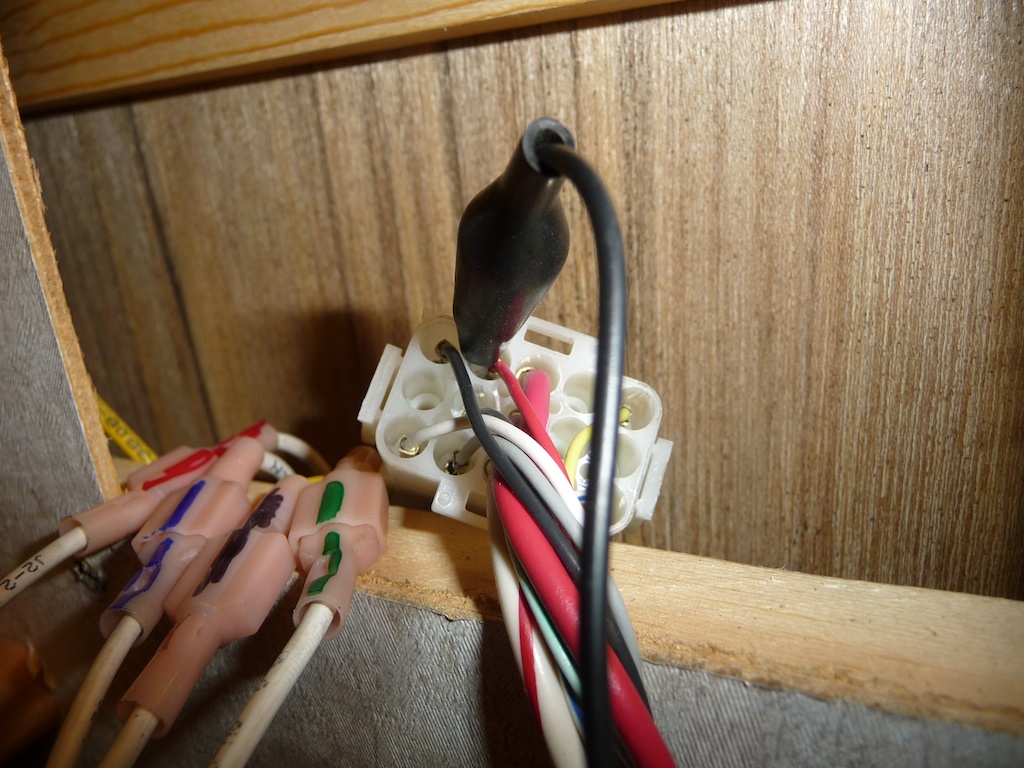
Third Switch wires spliced into original yellow water pump wires
|
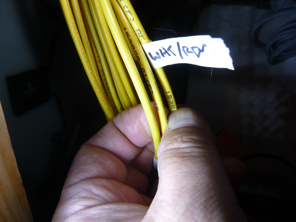
Which yellow wire? You'll need to identify just two wires out of this bundle for the modification
|
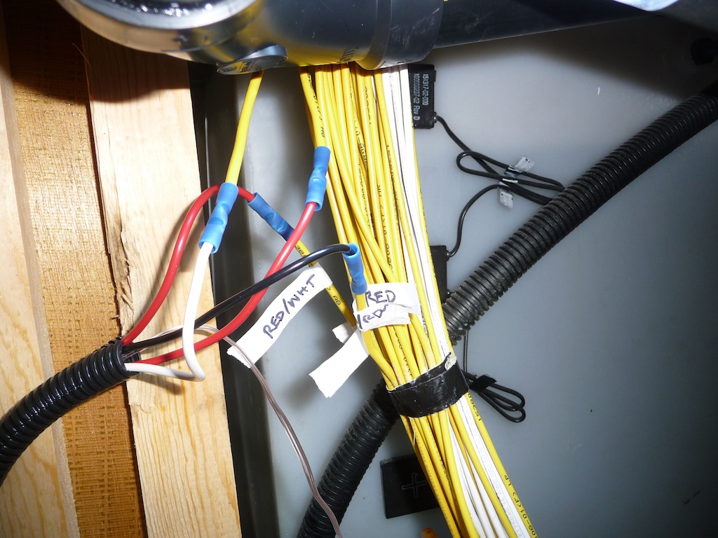
Wires located, I then marked the two switched pump wires with four labels at a convenient position for splicing work in the water heater compartment. I put two labels on each wire, identifying either the "A" wire or the "B" wire so that after the wires are cut, each free end will still be identified. I then cut the two wires and spliced a pair of long wires so that there were two long "A" wires and two "B" wires which can reach the new switch position. Put another way, I'm making a long additional loop in each wire which goes from one severed end of the "A" wire all the way to the swtich, then another run which goes all the way back to the other severed end of the "A" wire. The same goes for the "B" wire.
As a straightforward solution for wiring the new water pump LED indicator lamp, I simply spliced a piece of 26-gauge polarized 2-wire "zip cord" in parallel with the water pump's two power wires. In addition to the four pieces of 16-gauge wire for the new switch, this made a 6-wire bundle to route to the new switch and LED. I fed this wire bundle into a long piece of plastic split loom. The split loom helps to protect the wires from damage by exposed screws, staples and other sharp hazards, makes the bundle much easier to fish through openings and spaces, and makes for neater appearance.
(click and hold on images on this page to enlarge them)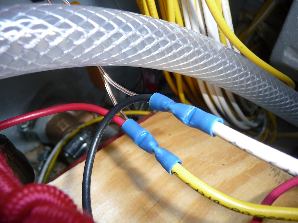 |
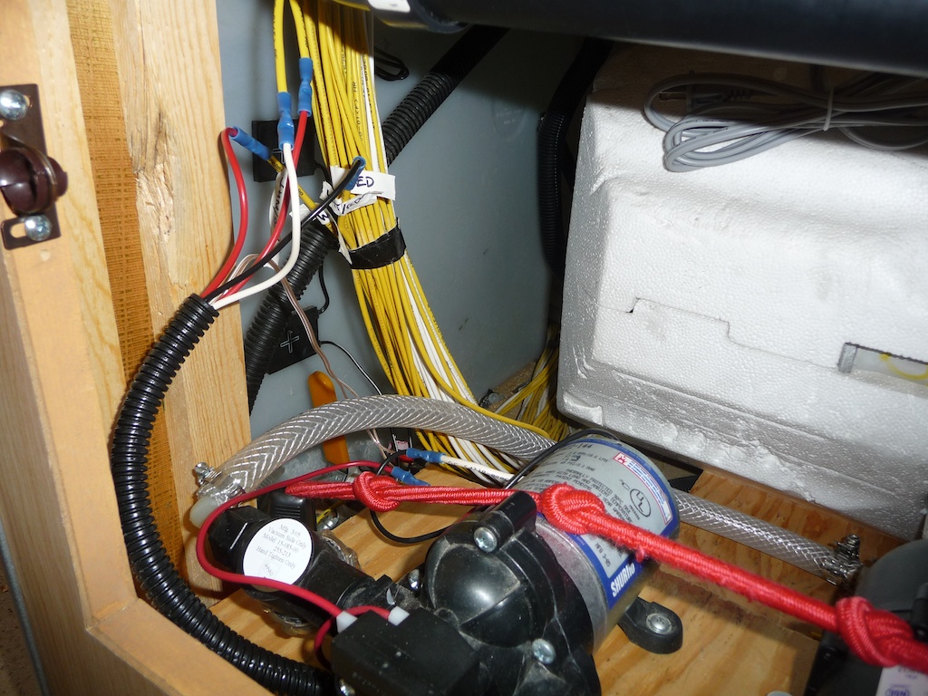 |
|
To the left of the blue butt splices, you can see the thin clear "zip cord" which powers the new pump LED
|
New wires for Third Switch enter split loom on the way toward the bathroom
|
I chose to route the split loom through the underbed storage area in our Navion 23J. This was done for ease of access, and because it neatly hides the loom. It required only one small opening between the water heater compartment and the underbed compartment, which was easily cut with a utility knife through the very thin luan used to skin interior volumes. I used nylon wire ties and screw-down anchors for wire ties to attach the loom to the perimeter of the underbed box, so it would stay out of the way of items stored there.
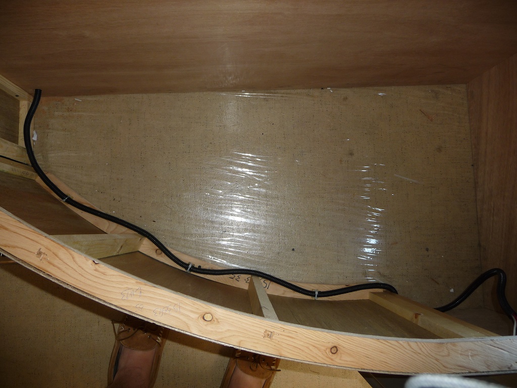 |
 |
|
Cable split loom routing around the base of the underbed storage compartment
|
New wires for Third Switch enter split loom on the way toward the bathroom
|
The wall between the bathroom and the underbed area is composed of very thin plywood "luan," covered with wallpaper. The luan is only 1/8" thick, and can easily be cut with a utility knife. Take care, as it is quite fragile where an opening has been created, and it would be easy to accidentally break the wood and rip the wall paper while working around the opening. Using the Contura "mounting bracket" as a template, I traced where the opening would be. The mounting bracket has plastic "barbs" which are spring-loaded and lock the bracket in place after it has been pushed into a close-fitting opening. However, it was designed for thicker walls - more than 1/4". So it did not securely anchor in the hole, sliding out at least 1/8" before catching the barb. To remedy this, I glued thin strips of wood on the inside edges of the wall opening to make it thick enough to engage the barbs. The barbs have several "stepped" surfaces so that they automatically adapt to different wall thicknesses, so there is some latitude in the necessary thickness of these wood shims - some experimentation will be necessary.
Inserting the switch body into the mounting bracket presses outward on the barbs, further locking the assembly in place. One-way barbs on the swtich body itself lock it into place. I don't recall what the nature of that mechanism is, but some study before installation may provide a strategy for removing the switch, should the need arise.
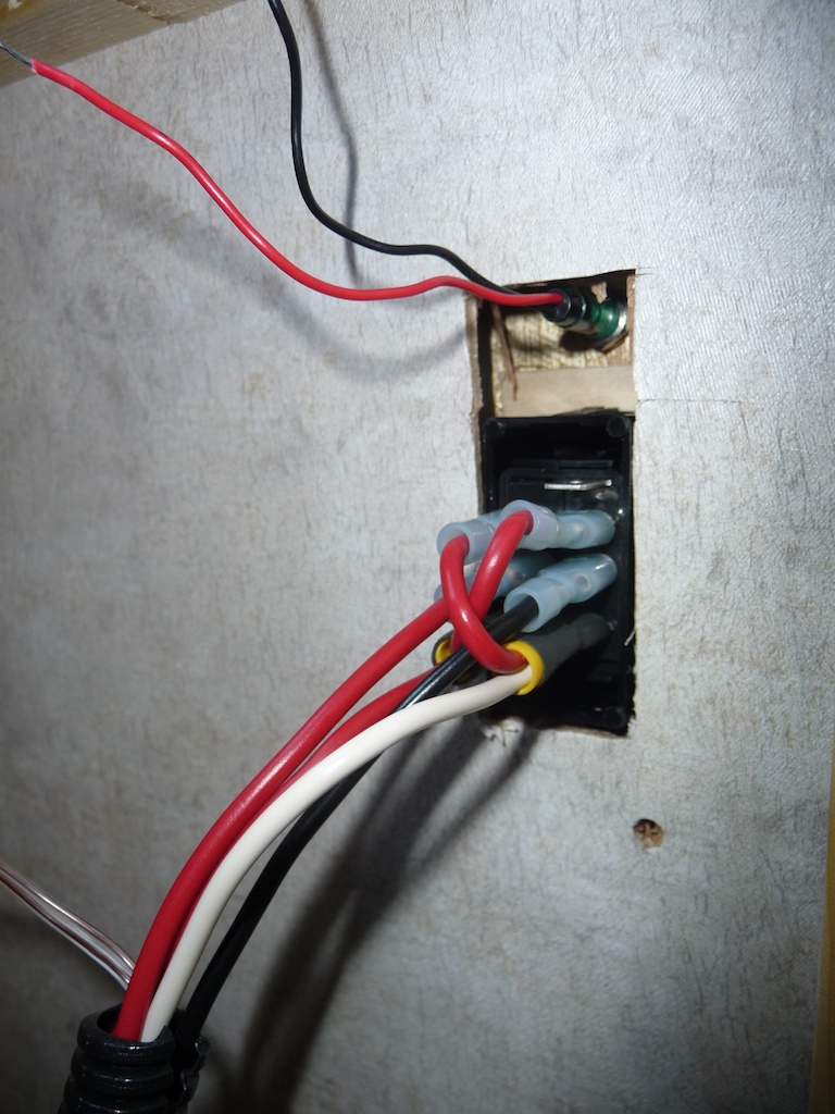
On the opposite side of the wall, I cut a slightly larger opening to make access to the switch's terminals easier. To locate the larger hole, I simply drilled a hole from the bathroom side through the middle of the switch opening. I then used a utility knife to cut a rectangular opening around the site from the underbed storage side.
Above the switch opening, I drilled a 9/32" hole to accommodate the LED, which is simply anchored by a friction-fit.
Even though it might be easier to connect the wiring to the switch before snapping into the hole (by feeding the wiring loom and connectors through the wall, then connecting the switch, then pulling the cable back through the wall until the switch is in place in the bracket), I installed the switch in the bracket without wires.
To the switch end of the new wiring harness, I prepared the wires by crimping female spade connectors in place, along with two short jumpers of wire which perform the trick of swapping the signals of the two wires (see "Wiring for the new Third Pump Switch" diagram above). This results in a total of (6) female spade connectors, which connect to the six male spade connectors at the back of the DPDT switch. I then plugged all the connectors to the switch.
I fed the LED's wires through the drilled 9/32" hole from the bathroom side and then pressed the LED into place. I then soldered and insulated the two 26-gauge wires which run in parallel from the water pump motor to the LED's wires, careful to get the polarity correct.
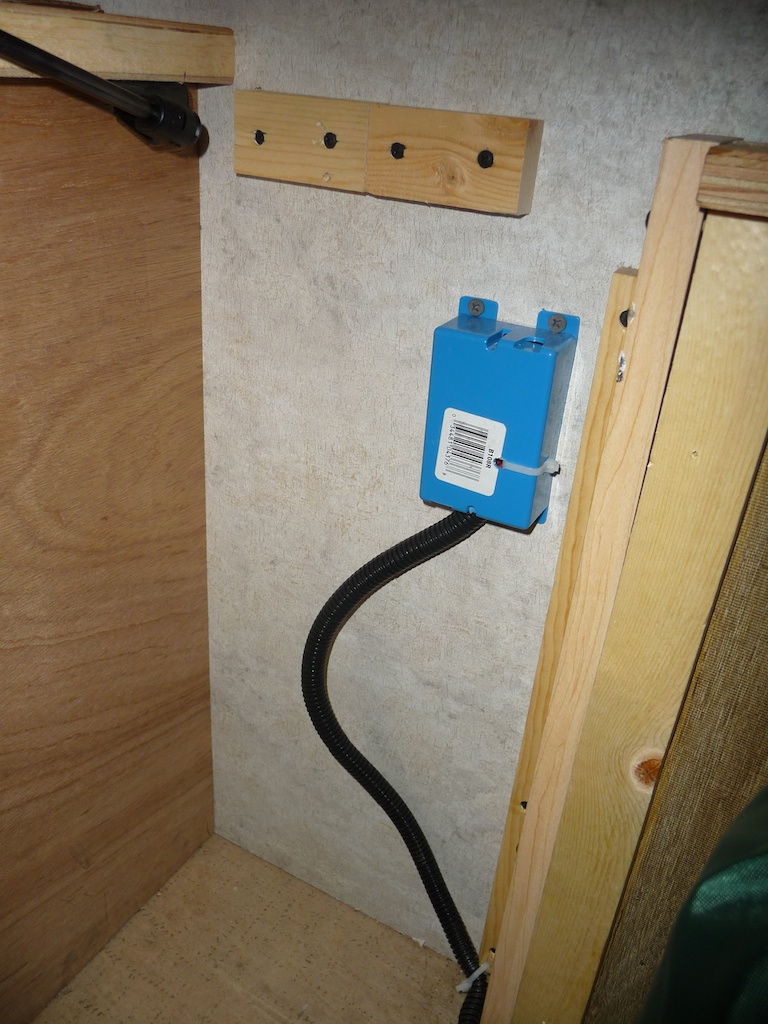
To protect the back of the switch and wire connections, I screwed a low-profile plastic electrical box (the kind installed inside walls behind AC wall switches and outlets) to the wall as a cover, passing the split loom through one of the provided knock-out openings in the box. A nylon wire tie passed through some drilled holes was used to secure the loom within the box.
 |
 |
|
Low-profile electrical box protects the switch connections from items in underbed storage
|
The pump LED lights when the pump is turned on from any of the three switch locations
|

 |
All contents Copyright 2013-2023 Ellsworth Chou |