| Modify your Winnebago View/Itasca Navion to sense the state of it's "house" door - and use your remote locking system with confidence |
|
by Ellsworth Chou
|
One of the persistent irritations of our (recently acquired) 2006 Itasca Navion is the behavior of the remote central door locking system and its interaction (or actually, lack of interaction) with the “house door.”
First of all, users of this year model of Winnebago View/Itasca Navion (I don’t know at this point what range of year models are affected) encounter the cryptic behavior where the central locking system refuses to respond to a “lock” command issued from the wireless remote key fob, unless the user first sends an “unlock” command.
A more significant problem is the possibility that the user can be locked out of the motorhome by the central locking system.
The remote locking system is designed to automatically re-lock the doors if the remote key fob was used to unlock the doors, but no cab doors are opened within about 45 seconds. Mercedes' apparent goal is to prevent the Sprinter owner from leaving the vehicle unlocked because they have accidentally activated the key fob - perhaps from within a building.
When Winnebago designed the View/Navion, they incorporated remote lock actuation from the Sprinter into the house door - a nice touch. However, they did NOT incorporate a system for sensing the open/close status of the house door (which would have been simple for them - as you will learn). So when a View/Navion owner uses the key fob to conveniently open the house door but naturally leaves the Sprinter cab doors unopened, the system re-locks the doors 45 seconds later. If the house door happens to be open at the 45 second mark, this activity might go unnoticed, but for the clacking of the locking mechanisms. If the house door happens to be closed, the next person attempting to use the door finds it locked. Should someone be unfortunate enough to enter, put down their keys inside, exit and close the door within 45 seconds, they’ll find themselves locked out.
More typically, users who have simply lived with the automatic re-locking when using the house door will find that their key fob remote’s “lock” function appears not to work after exiting through the house door, although it does flash the parking lights. This is because the Sprinter believes that the doors are already locked - blissfully unaware that the house door exists. So the only way to remotely lock the house door at this point is to first unlock the central locking system after which remote locking is possible. As a way of explaining the system’s behavior, even using a key to manually unlock cab doors at this point will signal to the Sprinter that the doors are unlocked, and remote locking is then possible.
Some View/Navion owners have learned to open and close the cab door within 45 seconds of using the remote to unlock the doors. This cancels the auto-re-locking sequence. Our family calls this “cycling the doors.” It was a real pain on our 40-day maiden voyage, and I was determined to fix the problem upon our return. The following documents my solution to integrating a door-sensing system from the house door into the Sprinter’s central locking system.
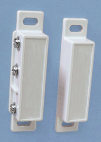
The solution is relatively simple. Closing a switch between two wires from the passenger-side cab door signals to the Sprinter’s central locking system that the door is un-latched. What I have done is to splice a pair of my own wires to these existing wires, and run them to the house door, where they are connected to a “reed switch,” just like the one you’ll find a few inches from the bottom of the hinge-side opening of the house door, which is used to actuate the retracting coach steps.
The solution turns out to be pretty easy to execute. You need a modicum of mechanical skills and an adventurous spirit. If you’re a View/Navion owner, you’ve probably got the latter.
Finding the solution was a bit tricky. I was too impatient to order a set of wiring schematics, so I diagnostically tested the six wires connected to the latch assembly inside the passenger door. Fortunately for you, I’ve done that work, so your task is quite a bit simpler.
|
|
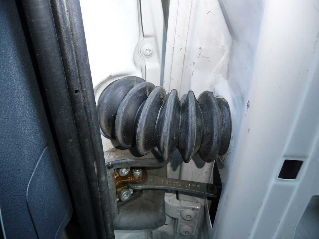
The easiest way to access the wires on which to splice the new door sensor (the magnetic reed switch) is at the hinge opening of the passenger-side door.
|
|
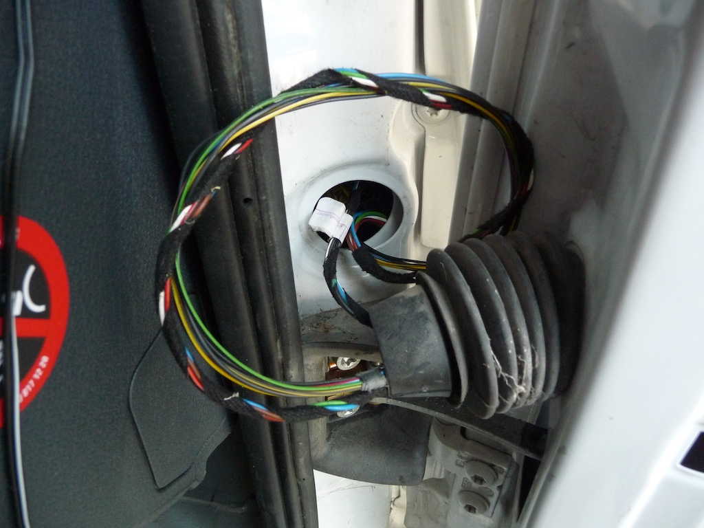
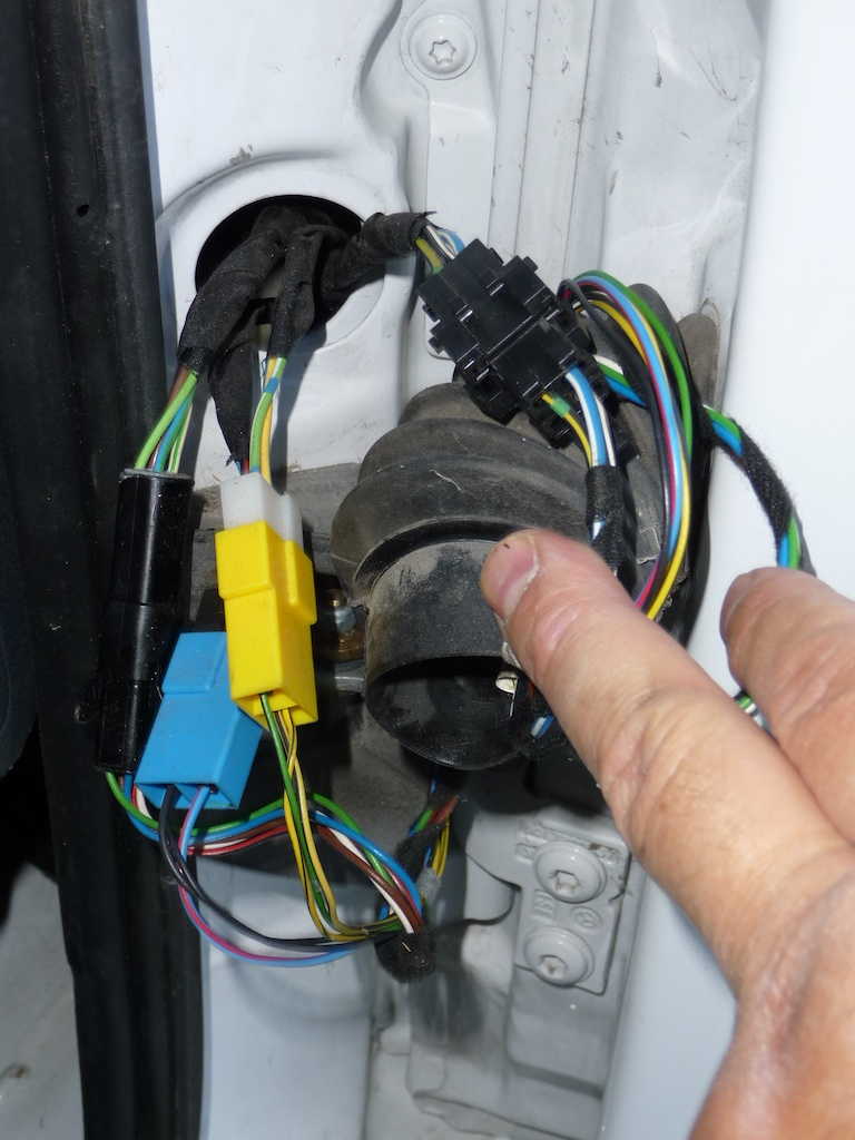
Open the passenger door fully. Pull the black rubber wiring boot from the door opening, exposing four bundles of wires. In our Navion, there was over a foot of slack in the wires stored loosely inside the right front fender. By gently pulling out the wire bundles, eventually four different pairs of plastic connectors are revealed, which can be extended out into the space between the door and door opening. It may be helpful to reach under the dash inside the vehicle and feed the other side of the wiring harness (all taped together as a single bundle at this point) to provide working slack at the door hinge opening. The wires of interest in our Navion fed into to a white plastic 2-conductor connector from the chassis, and into a yellow connector on the door side cable.
|
|
I was able to pull the wires with yellow/white connectors about 6 or 7 inches clear of the fender opening, giving me slightly cramped access to the wires. I chose to splice into the wires on the fender side harness, so that in the unlikely event that the door is eventually removed for service, the body shop can disconnect the connectors as intended, without being impaired by my new pair of wires.
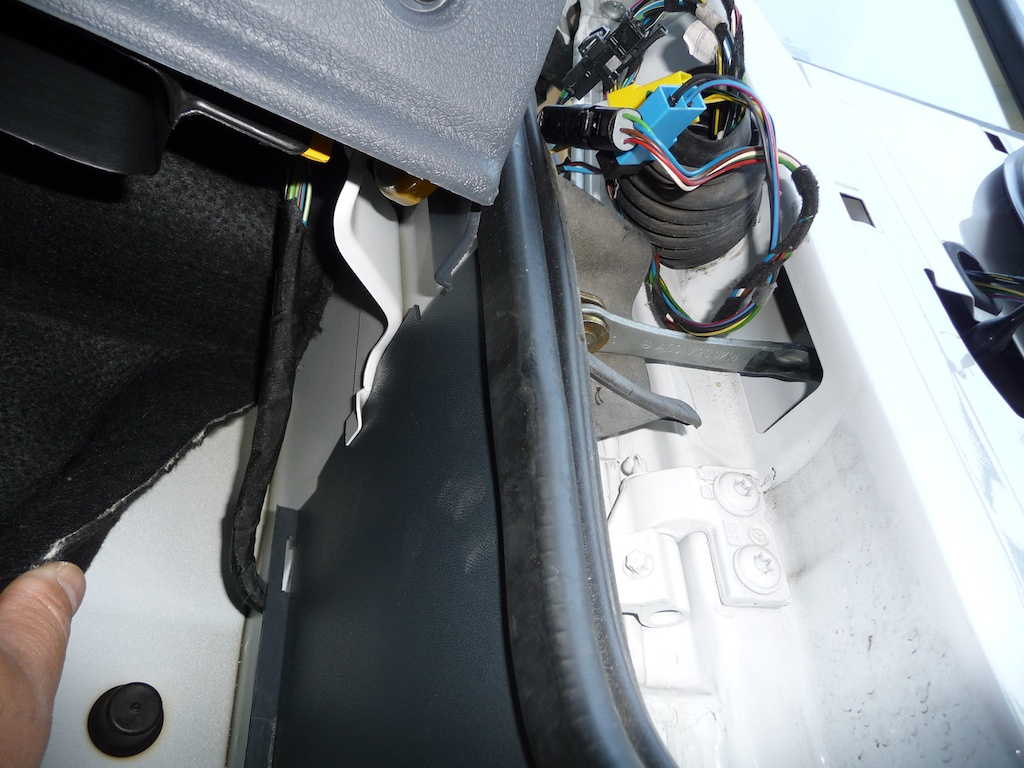
Splicing the wires at this point - a few inches from the white connector in the image below - means feeding the new wires from inside the cockpit, under the dash, and out through this same wire opening from which I extracted the cable bundles. I accomplished this by poking a straight rod through the fender opening and out under the dash, through a hole in the right side of the passenger footwell. To improve access to this interior opening, I removed the Sprinter's tool box cover from the floor of the passenger footwell (under the floormat/carpet), and gently pulled back the black felt-covered panel which decoratively hides sheet metal and wiring under the dash. Shining a light source through the footwell hole made it easier to aim the rod. I then taped the end of my wire to the end of the rod under the dash, and withdrew the rod, drawing the wire through the fender and out to where the wire bundles were.
(If you don't mind working under the dash, you could alternately perform this splice entirely under the dash, never working with the harness in the door opening, and obviating the need to feed the new wire through through the bodywork.)
 |
|
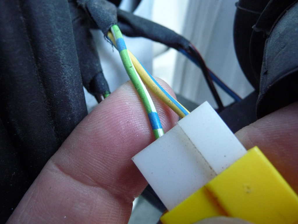
Detail of the passenger door latch sensor wires to which new reed switch is connected
|
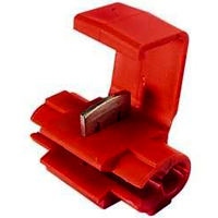
The existing harnesss wires to which the new wires are spliced are color-coded: 1) yellow with a blue trace and 2) green with a white trace and blue dashes (see image above). I chose to strip, splice, solder and insulate my new wires, but you can save yourself a lot of headache and time by using 3M Scotchlok™ quick connectors. You can find these in auto-parts stores - they're commonly used to add accessories to existing wires without having to cut the original wires. The connectors bite through the original wires' insulation and also into the end of a new wire to make an insulated connection without cutting, stripping or soldering. Here is a Web page that demonstrates the use of this type of connector. You'll need a model of Scotchlok™ which accommodates the range of gauges of both the existing and new wires - the "18-22AWG" size connectors are color-coded red (larger connectors are color-coded blue and yellow).
To test that the wires are properly spliced, and to the correct part of the harness, do the following:
|
|
|
After making the splice, I wrapped about a foot and a half (closest to the splice) of my new two-conductor wire with cloth "friction tape" to give it additional protection against the potentially sharp edges of the sheet metal holes through which I'd just passed the wires.
That's the hardest part of the operation. Feed the connectors and cables back into the fender opening, and re-insert the rubber boot, being careful to get the boot to seat fully so that it doesn't bind or bunch when the door is closed.
Now run the new wires to the edge of the house door frame. I fed the wire up from the passenger footwell alongside the right outboard side of the dash. The plastic trim covering the "A-pillars" on the left and right side of the windshield are retained by reversible latches - simply grasp the plastic cover with both hands and pull toward the opposite pillar, and it will pop off. Once this cover is removed, you'll see that there are other wires already hidden alongside the A-pillar.
I chose to hide the wires inside the cockpit ceiling panels above the passnger side door. Pulling off just the top edge of the rubber door seal for the passenger door frees up the panel enough to be able to get a few fingers between the panel and the sheet metal above the door opening. By removing the two screws inside the chrome snaps which retain the passenger side of the cockpit privacy curtain, and then the rearmost six of the white-painted screws holding down the top of the passenger-side plastic molded tray under the bed, I lifted the plastic cover enough to feed a long rod all the way down to the top of the A-pillar. Again I taped the free end of the new wire pair to the rod, and drew it all the way to the curtain snaps.
|
|
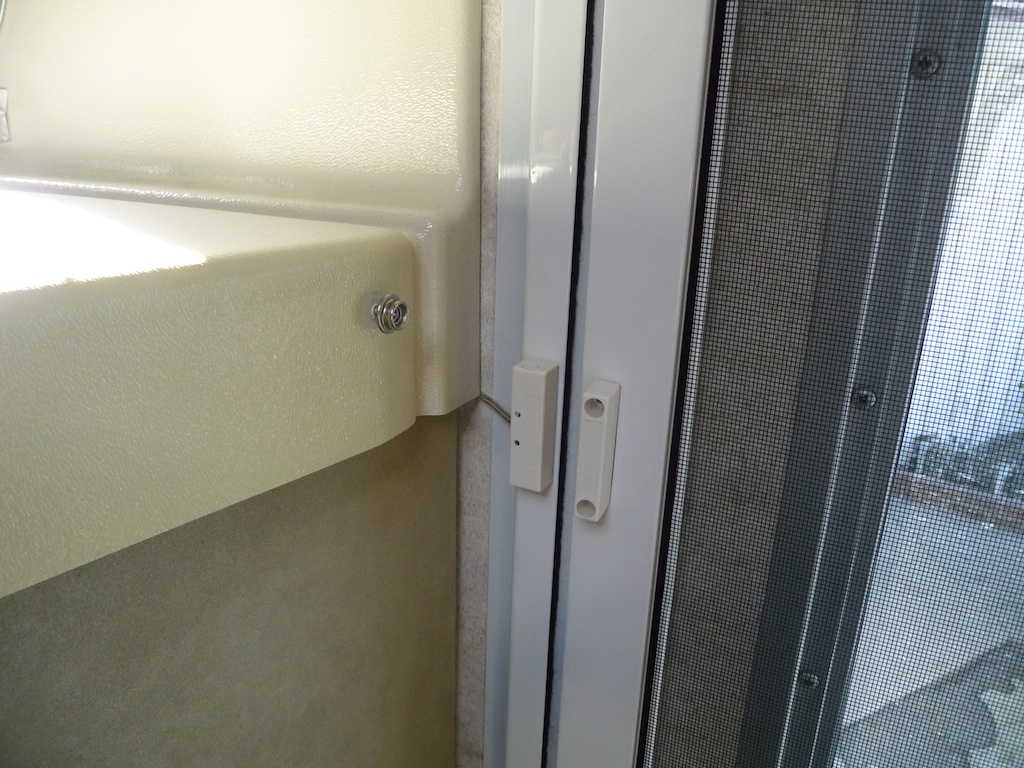
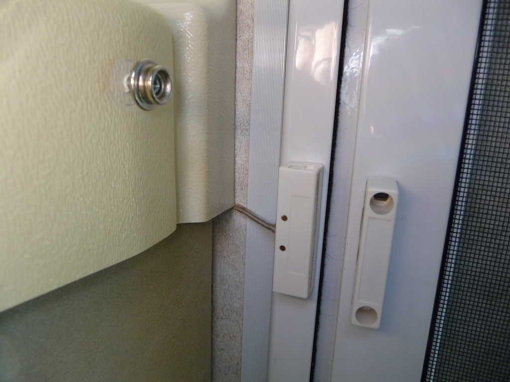
For simplicity, I used Scotch 4011 Exterior Mounting Tape to mount both the reed switch and magnet to the door frame and the inside of the screen door. Screws can't be used on the frame edge adjacent to the door, because the weather seal and door are immediately on the opposite side. Winnebago's solution is to tack-weld a piece of metal to the door frame to provide a place to bolt the reed switch for the retractable steps. The Scotch double-stick foam tape is really robust - and should give many years of service.
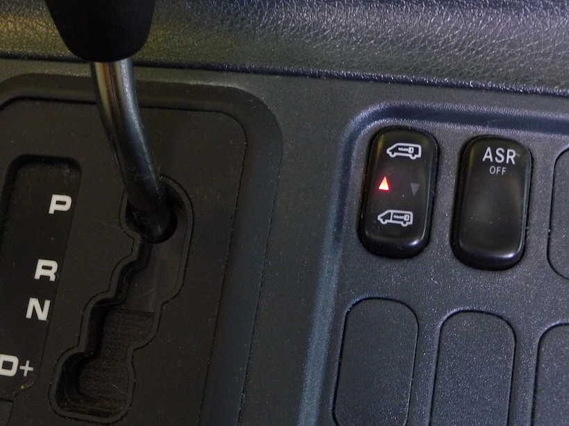
By listening for the quiet "tink" of the reed in the switch as I moved the magnet closer and further, I judged an appropriate distance to mount the magnet from the switch. This will vary with any given switch. In the final installation, the door opens about five or six inches (measured at the door opening, not the reed switch) before the sensor is triggered - perfect. Once the switch is wired, you can watch the passenger-side central locking switch indicator - it should flash whenever the house or passenger cab doors are open.
That's it! I tucked the wire under the plastic bed-tray and restored the tray's screws, careful to avoid the new wires.
The modified Navion's central locking behavior is fantastic - just as it should have originally been from Winnebago. The central locking system honors the state of the house door just as it does the passenger cab door. No more unintended automatic locking. The remote key fob works just as you'd expect, without ever opening a cab door.
NOTE: By design, if the central locking system is given a "lock" command when a door is open, the locks will lock, then immediately unlock as a way of indicating to the user that a door is open. This behavior is now extended to the house door.

 |
All contents Copyright 2013-2023 Ellsworth Chou |