![]()
Fabricating Replacement Shift Paddles on the Logitech Wingman Formula Force
...and never break a paddle or shift switch again
| This page describes some of the process of replacing the stock plastic shift paddles of the Logitech Wingman Formula Force with handmade steel paddles, and the Logitech fault-prone original PC-board shift switches with rugged microswitches.
This is not a set of instructions, but a loose photojournal of some stages of the fabrication. If you decide to undertake this task, it can be accomplished in many ways. This is neither the hardest, easiest, quickest or best approach - it is merely the one which evolved as I designed it. Your results may vary. Best of luck. - Ellsworth (click on any images on this page for larger image) |
Modify the Logitech Wingman Formula Force to connect Act Labs Performance Pedals as "built-in"
UPDATED 4/26/05! Modifying Act Labs Performance Pedals with unbreakable compression springs!
| Contents |
|
Why fabricate replacement paddles?
The shift switches on both of my LWFFs began to fail on the right (upshift) side, causing both missed shifts and sometimes multiple shift inputs from a single actuation of the paddle. Intermittent shift response probably led to the right paddle itself breaking on one of the wheels. I'd planned long ago to fabricate replacement paddles if and when this occurred. I'd somewhat recently installed one of Jens Schumacher's thoughtfully crafted LWFF ball-bearing conversion kits, so one LWFF is even *more* valuable to me as my sim controller-of-choice. If successful, this modification would eliminate shift hardware maintenance. Additionally, my plan to use microswitches promised much crisper shifting action.
|
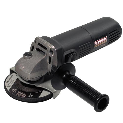
This was accomplished primarily with common hand and power tools, with the possible exception of an angle grinder (see photo at left). I'm not a professional metal-worker, but have done quite a bit of fabrication for small personal projects. I don't have a proper metal-working shop, and lack many useful large tools (band saw, drill press). On many projects, including this one, I end up with less-than-perfect precision, partly due to limited tools, partly to lack of real training in the craft. However, I typically allow for this in my long planning process. If you're handy with working metal, you might be able to accomplish this. If not, perhaps you have a friend who can help. |
(Some of these items can be found at your local Radio Shack. Where applicable, I've included part numbers and prices.)
The Process (click on any image to enlarge)
I rough-cut the steel stock into two 4" squares. I then traced an outline of an original paddle onto one of the blanks.
 |
|
|
rough cut blank to the paddle width.
|
traced paddle shape
|
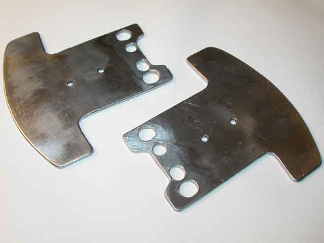
The blanks were pop-riveted together during the cutting and grinding process. I hacksawed the rough outline, then used the angle-grinder to get close to the final shape. Drilling and using a Dremel Moto-Tool (small very high-speed grinder) shaped the holes. Some trial-and error fitting into the wheel was necessary, as the final shape of the inboard end of the paddles is quite complex. After the shape and holes were finalized, the rivets were drilled out and the two matching paddles were smoothed and rough-polished on a bench grinder wire-wheel. Where practical, the holes were chamfered by drill bit or Moto-Tool.
 |
|
|
two blanks riveted together for rough shaping
|
paddles after separating
|
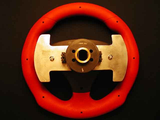
I made the odd choice of not modifying the plastic body of the Logitech wheel, instead making this somewhat complex piece of metal to be located by, and hinge upon the existing plastic moldings. No significant forces are put into these plastic pieces in the assembled wheel.
 |
 |
|
the final shape is a close fit
|
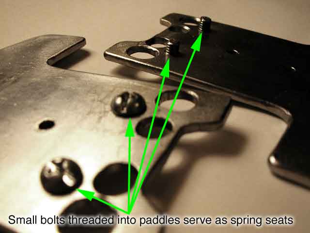
short bolts keep springs ends in place
|
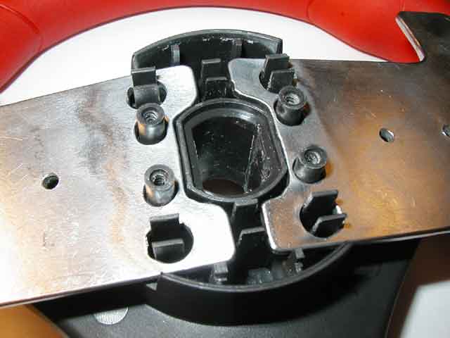
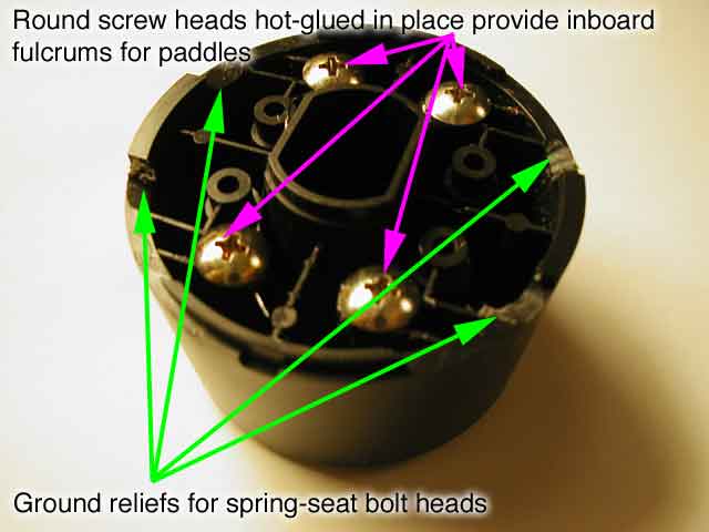
The plastic wheel hub (below left) did require grinding some relief grooves after I realized the need to add short bolts to the paddles to locate the paddle ends of the springs. Phillips-head screws serve as fulcrums against which the paddles actually bear their operating load, and without them, the paddles would also angle away from the plane of the wheel. Stiffer and longer paddle springs found at a hardware store turned out to be the perfect tension.
 |
 |
|
detail of grooved hub and fulcrum screws
|
detail of paddle spring seat bolts
|
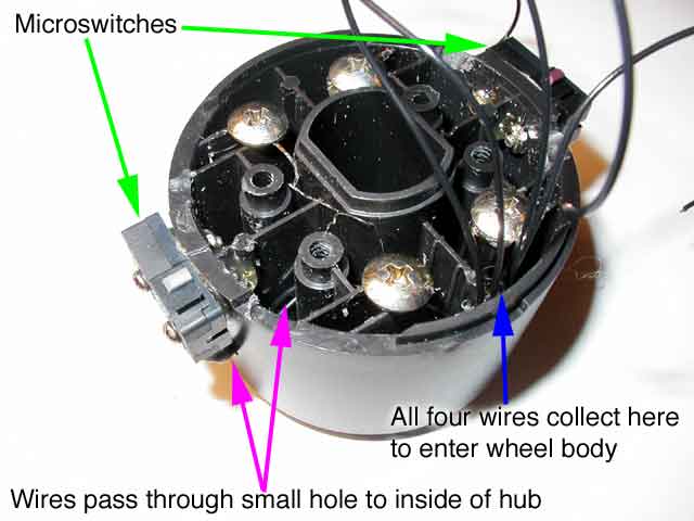
The right and left microswitches were temporarily hot-glued (below left) into place at 9 and 3 o'clock so the "button" side is flush with the part of the hub on which the paddles rest. Then holes were drilled through the glue into the hub for the tiny bolts/nuts which secure the microswitches. The hot glue serves to provide a fillet between the cylindrical side of the hub and flat sides of the switches. The button protrudes into the space the paddles occupy at rest, so the switches are depressed until a paddle is moved 3-4mm, when the switch is released. Wire a pair of wires to the "C" (Common) and "NC" (Normally Closed) terminals of the switches - the "NO" (Normally Open) terminal is ignored. Holes drilled into the sides of the hub on the terminal sides of the microswitches allow the wires to pass into the hub, where all four wires (two left, two right) exit at a 6 o'clock position. Small dabs of hot glue secure the wires into the hub.
A 3/16" (5mm) hole in the body of the wheel (below right) allows the switch wires to pass through to the printed circuit board inside the main wheel body.
 |
 |
|
switches mounted and wires routed
|
hole to pass switch wires through wheel
|
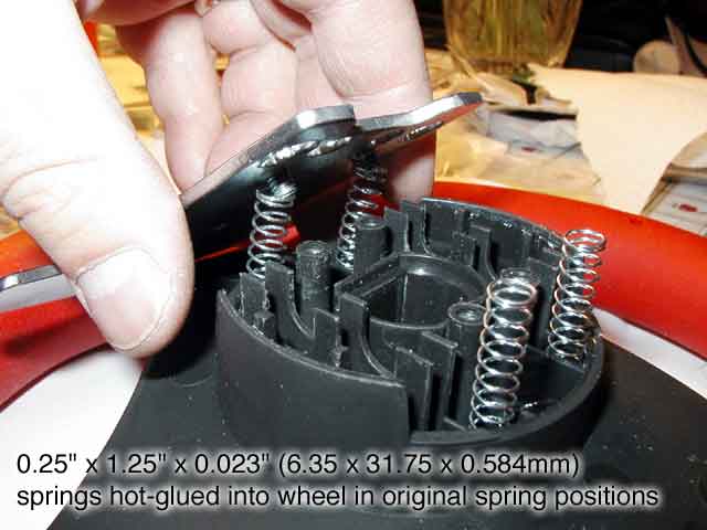
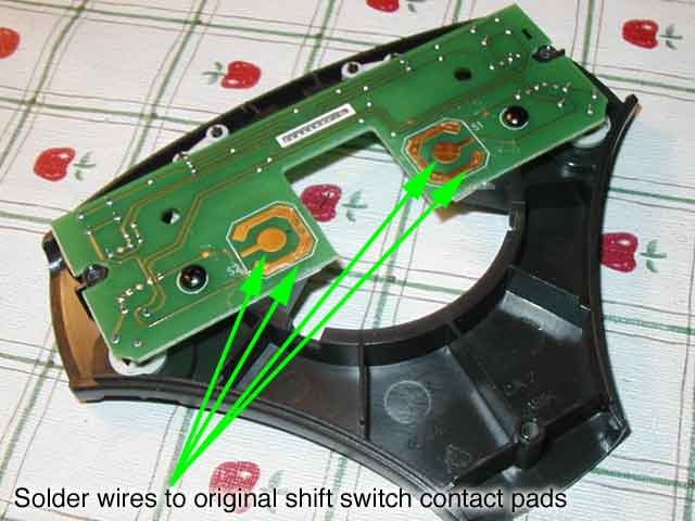
A fair amount of wire (15" or 40cm) should be run from the microswitches in the hub to the printed circuit board inside the wheel, to allow assembly/disassembly. Peel the clear tape and the chrome-plated discs which act as the original spring and switch (and in the case of a faulty switch, will probably be split in the middle) and discard, exposing the gold-plated contact pads (lower left). Solder the appropriate pair of left and right wires from the microswitches to the right/left gold pads. Polarity of the two wires from each switch is NOT important, but left/right is critical. Take your time here - it can be confusing to determine which microswitch or pad is on the left or right in the final assembly. Though you can probably reconfigure left/right paddles in every piece of software, you might as well get it right.
 |
 |
|
solder pad locations for switch wires
|
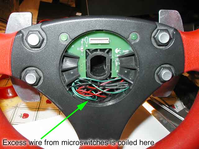
coiling the excess switch wire
|
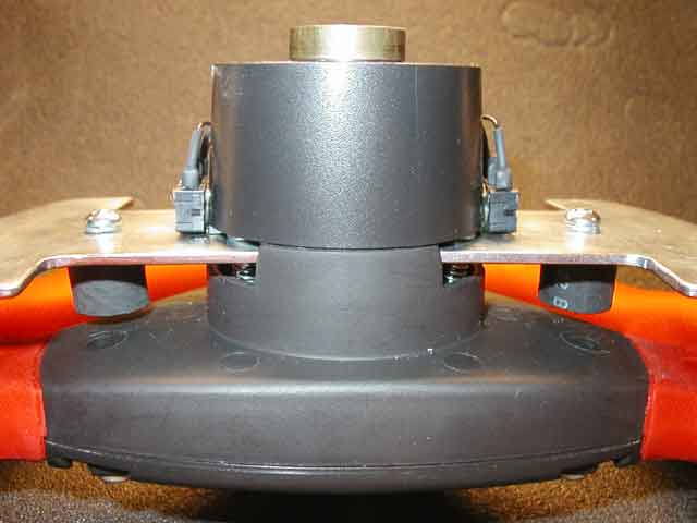
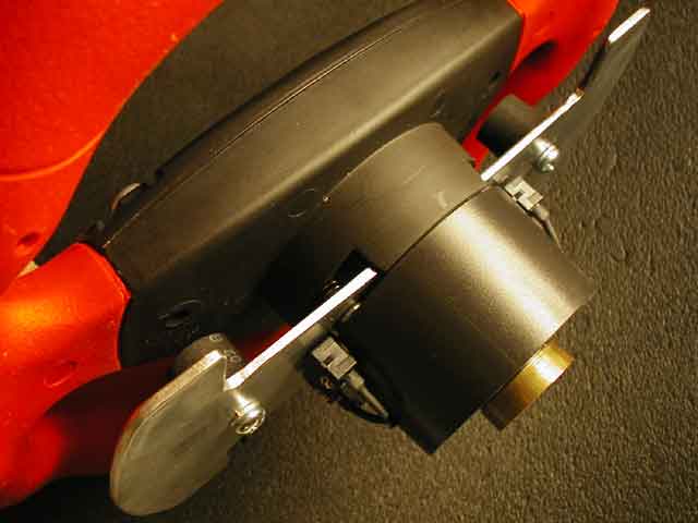
After test-driving, I realized that the paddles really needed stops. Without them, they travel all the way to the wheel rim. Not only does this take some time to become accustomed to not having a "stop," I discovered that I shift only with my index fingers, pinching my middle finger with the paddle several times a lap. I used some automotive heater hose, hot glue and nuts, bolts and washers to make stops, which can be seen below. The final result is a nice "thud," giving feedback to the driver that the shift has completed, while providing a margin of safety against over-enthusiastic shift pressure. Total travel at the outer edge of the paddles is 8-9mm (1/3").
 |
 |
|
top view of final assembly
|
final assembly
|
I'm very pleased with the final paddles. The shift action is positive and quick - it's possible to create shift inputs as fast as your finger(s) can move. The stops provide a solid "thud" to signal that the lever has reached its travel limit. And I'm very pleased knowing I'll (hopefully) never have to worry about broken paddles or shift switches again.
A Better Alternative
In January of 2007 I purchased a Logitech G25 Racing Wheel. Though the steering mechanism isn't as smooth as the Logitech Wingman Formula Force, its 900-degrees of turning lock was much too compelling, and I never returned to the Logitech Wingman Formula Force which I'd spent so much effort improving. Five years later, the G25 continues to serve well, with the exception of a failed reverse switch (which was remedied with a replacement shifter). The G25's shift paddles - made of steel, like the ones I made here - have proven to be very durable. I do miss the "thunk" of my own paddle mechanism, though. I wrote a this long-term review of the Logitech G25 in 2008.
Contact
 |
All contents Copyright 2004 Ellsworth Chou |
|